In this tutorial I will explain in details how to bring a model from Blender to Dark Places engine (DP in short) via .DPM file format. DPM is a native to DP format that can contain non-animated or animated models. Since DPM was invented to contain skeletal animation, even non-animated or static models, have to have bones.
For this tutorial we assume that we already have a model, UV-mapped and textured.
Instead of operating with abstract models, we will replace old Quake armor with new one.
You have to keep in mind that Blender can not directly export to .DPM format, but it can export to Doom 3 .md5 files. We are going to use it as an intermediate format that can be converted later into .DPM file.
Following are supplemental files that contain models, textures and a special utility what will allow us to process Doom 3 .md5 files and create .DPM file that will be used with DP engine.
armor_models.zip - contain texture for the final model of armor, various .blend files with models and .blend file of template scene
tmrf2dpm.zip - Doom 3 to DPM conversion utility.
To view the results, I encourage you to download and install Quake shareware (unless you have full version already installed) prior to following this tutorial.
Let us begin!
First of all un-zip armor_models.zip into c:\games\quake\ (or wherever you have Quake installed) and un-zip tmrf2dpm.zip into c:\tmrf2dpm\
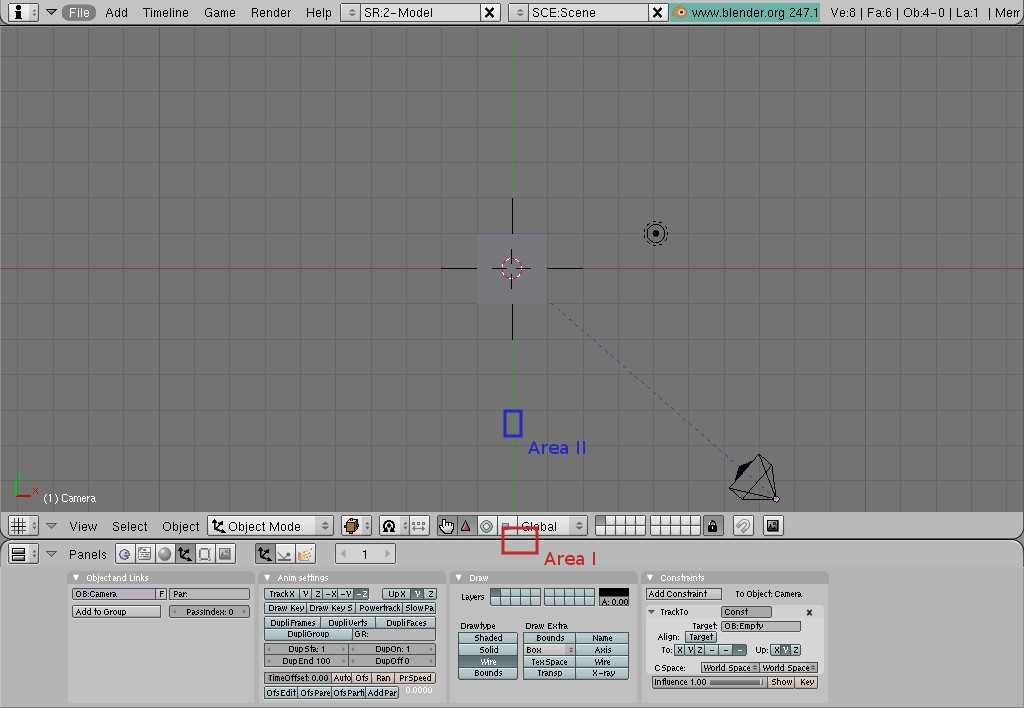
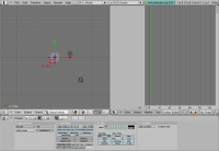
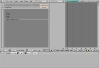
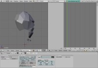
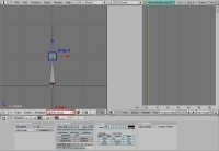
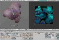
Fire up Blender and you will see default layout similar to what you see on Pic. 1. |
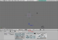 |
Pic. 1 |
|
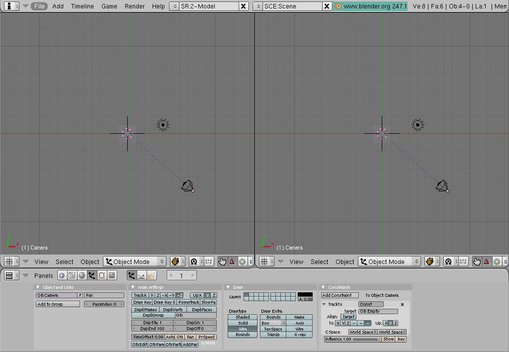
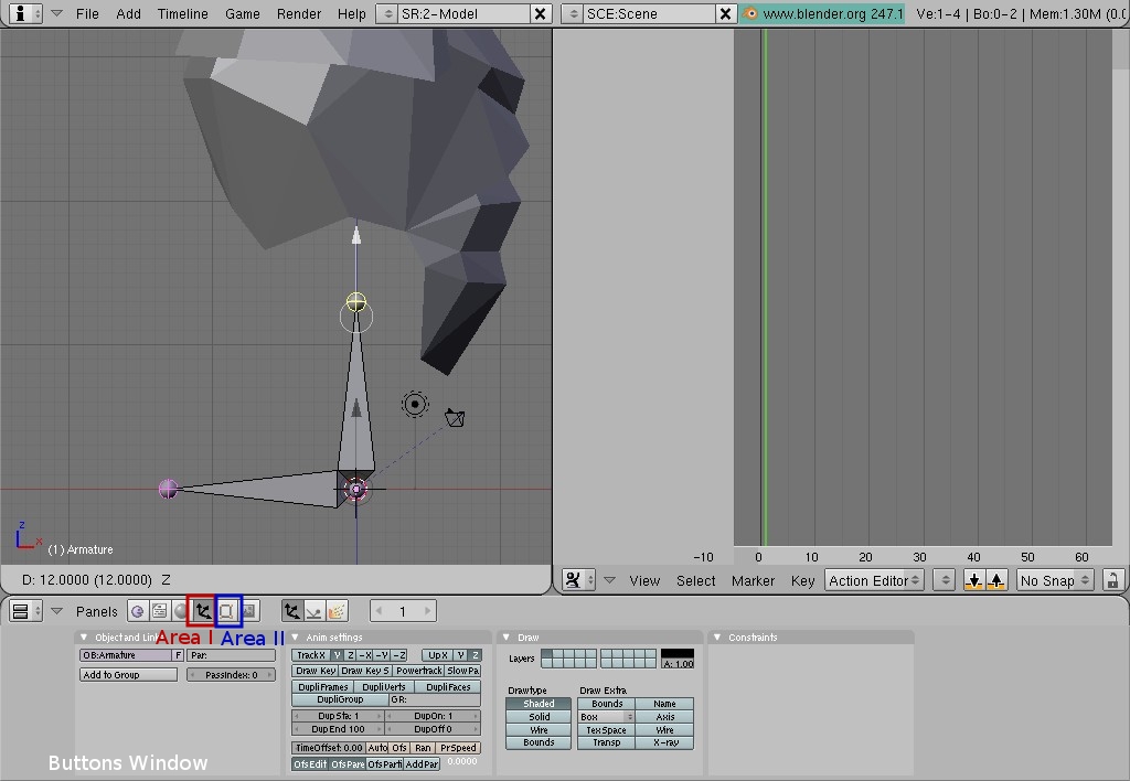
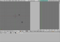
| Let's split 3D View in half. Right-click on the border between 3D View and Button window (Pic. 1, Area I). Select "Split Area" from the appeared dialog and left-click on it. Position a bar that follows mouse cursor right in the middle of the 3D View (Pic. 1, Area II) and left-click to finalize the operation. Now we have two identical 3D Views (Pic. 2). |
 |
Pic. 2 |
|
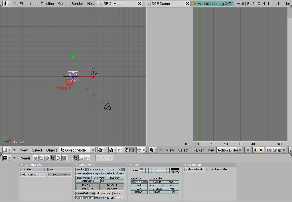
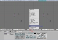
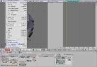
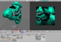
| We are going to turn right 3D View into Action Editor (same thing as Dope Sheet in 3DS MAX). Let's click on the icon at the bottom left corner of the right 3D View (Pic. 3, Area I). Choose "Action Editor" from the pop-up menu and left-click on it (Pic. 3, Area II). There you go, now we have 3D View on the left side of the screen and Action Editor on the right (Pic. 5). |
 |
 |
Pic. 3 |
Pic. 5 |
|
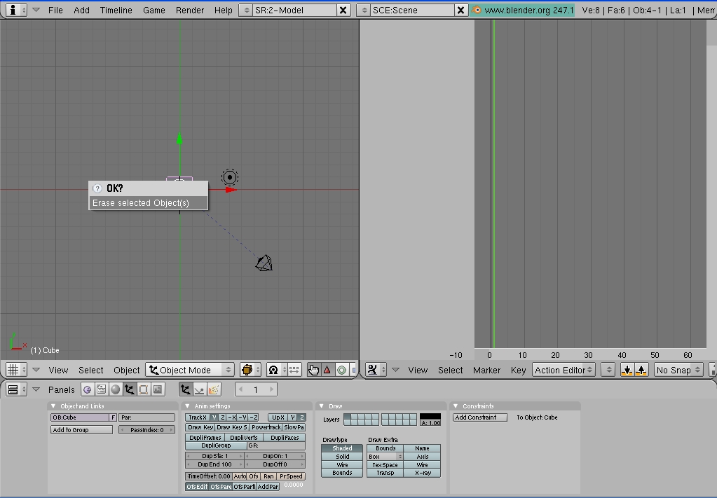
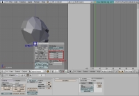
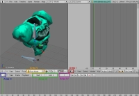
| If you noticed, we have a cube (default mesh) that has been in 3D View from the moment we started Blender. We are not going to be using it, so let's delete it. Right-click on the cube. It will become highlighted with pink contour (Pic. 5, Area I). Press X or Delete key and click on appeared dialog, or simply press Enter (Pic. 6). Now we are ready to bring a model in (Pic. 7). |
 |
 |
Pic. 6 |
Pic. 7 |
|
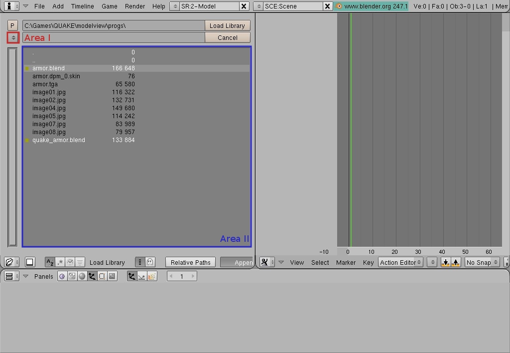
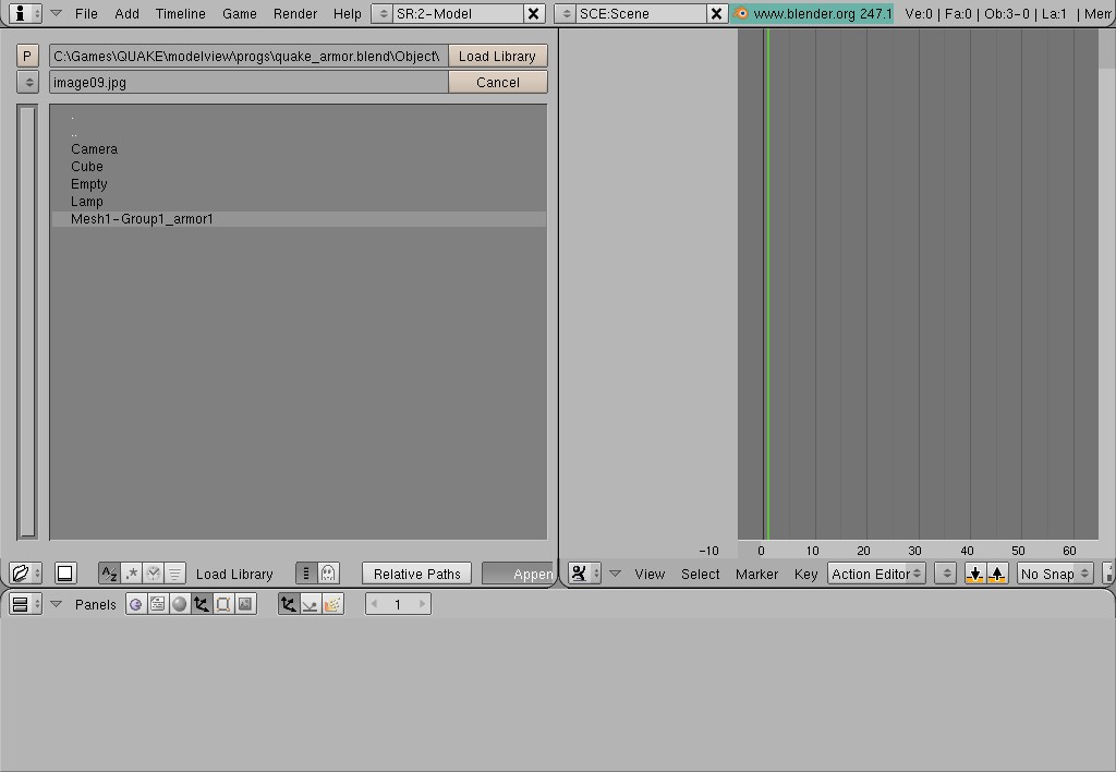
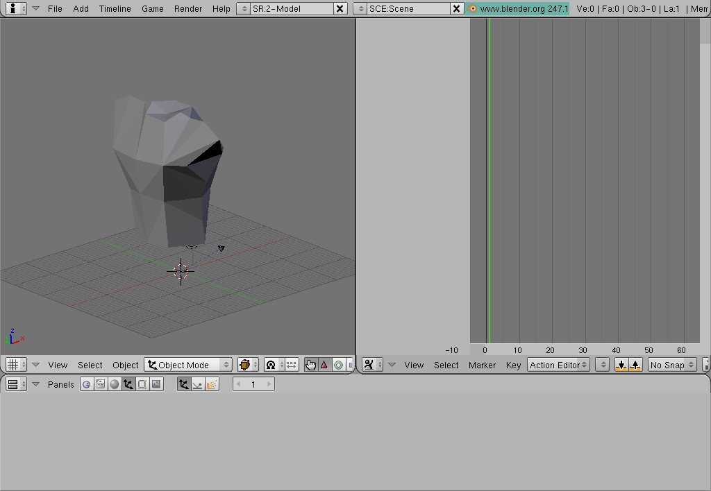
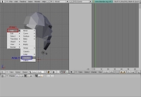
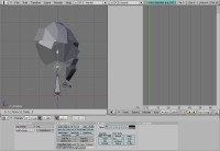
| Move mouse cursor into 3D View and press Shift + F1. File browser dialog will appear. Locate your QUAKE\armor\progs\ folder (use Area I on the Pic. 8 to select and drive or last visited folder, and Area II to browse folders / work within a folder). Click(?) on the file named "quake_armor.blend". When we are in the Library Linking mode(?) Blender will treat .blend files as folders to allow us to pull its' content in our working scene. Once you are inside quake_armor.blend, you will see various sub-folders. Go to the Object folder (Pic.9) and double-click on Mash1-Group1_armor (Pic. 10). The original Quake armor model will be loaded in Blender and you will see it in the 3D View (Pic. 11). In this particular case we need original model in order for us to determine scale and position of the replacement model. |
 |
 |
 |
 |
Pic. 8 |
Pic. 9 |
Pic. 10 |
Pic. 11 |
|
If you would like to see the model you just loaded in the Perspective, follow the sequence:
Move mouse cursor into 3D View -> Press and Hold mouse wheel -> Move mouse around a bit to determine most pleasant angle of view -> Release mouse wheel. You should have something similar to Pic. 12 on your screen. |
 |
Pic. 12 |
|
Let's bring a replacement model in too. To do that follow the sequence:
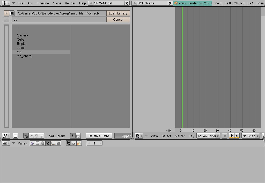
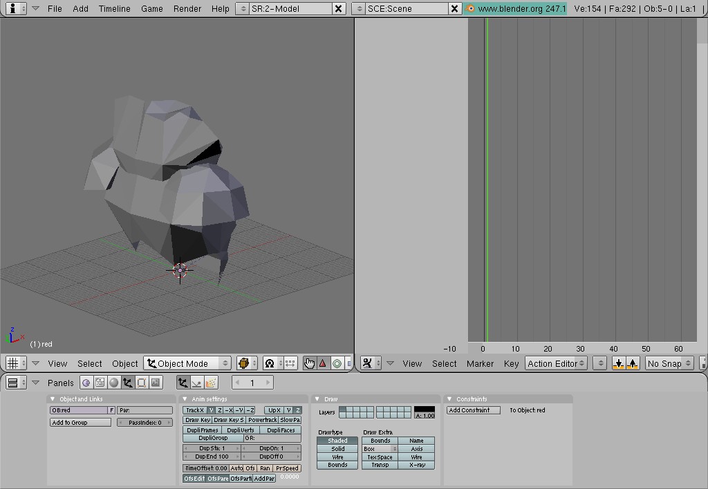
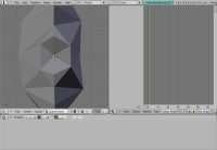
Move mouse cursor inside 3D View -> Press Shift + F1 -> Locate your QUAKE\armor\progs\ folder (if not already in it) -> find a file named "armor.blend" and click on it -> go to the Object folder -> double click on "red' (Pic. 13).
As you can see, now we have another mesh in 3D View (Pic. 14). The model we just brought in is originated from Quake 3 Arena. The replacement model is offsetted relatively to the original model. Let's move new armor a bit up.
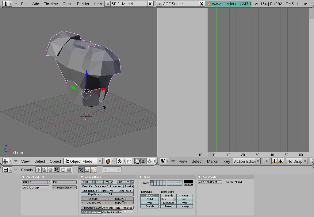
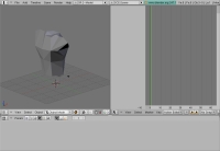
Follow the sequence: right-click on the new armor (it will become highlighted with pink contour) -> press <G> key -> press <Z> key -> move mouse up and match new armor position to the old one (Pic. 15). Once desired position achieved, left-click to finalize operation and press <A> key to de-select all objects in the scene. |
|
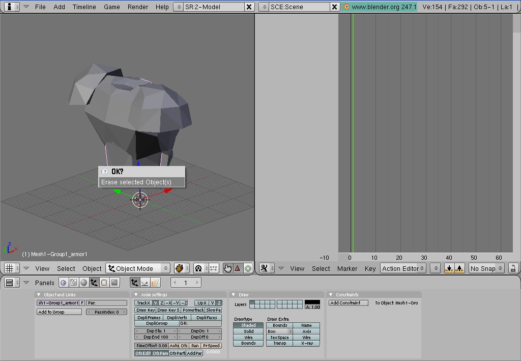
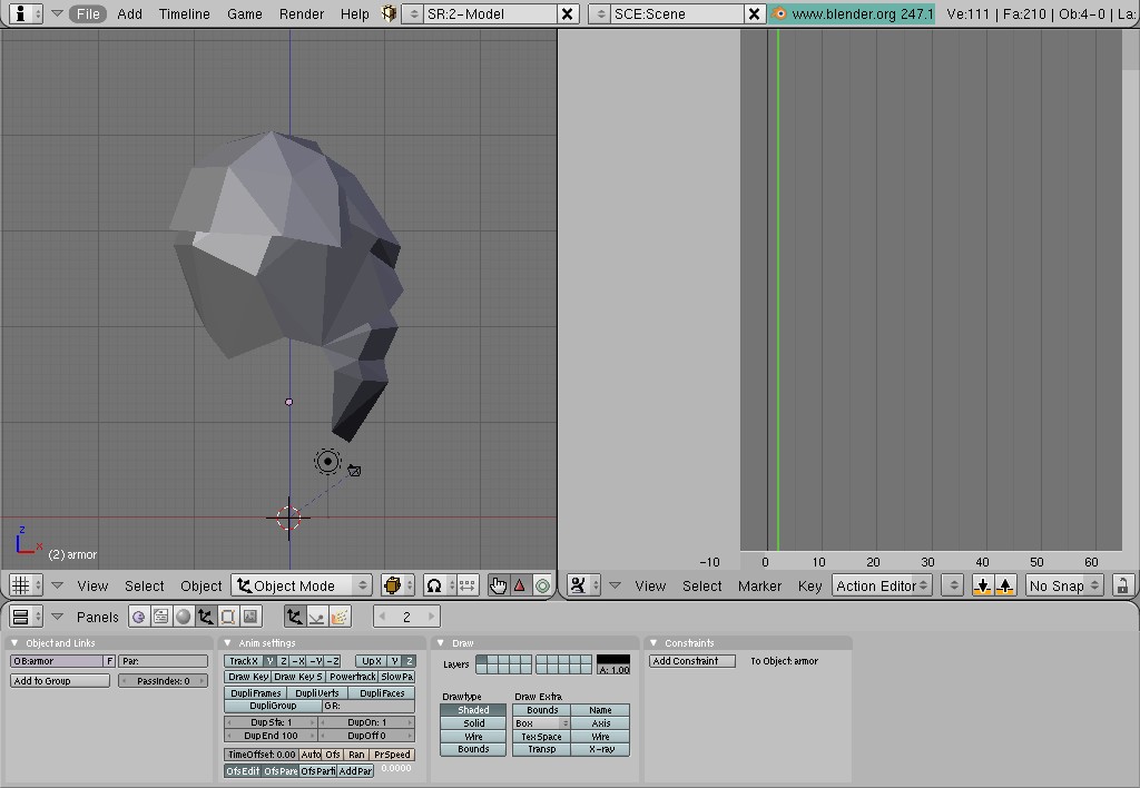
| It's time to get a rid of the original armor. Move mouse cursor right above any visible part of the Quake armor and right-click to select it. The mesh should become highlighted with pink contour. Press <X> or <Delete> key and confirm pop-up message (Pic. 16). With mouse cursor within 3D View, press <1> key on the keypad to switch to Front view (Pic. 16a). |
 |
 |
Pic. 16 |
Pic. 16a |
|
We are ready to do some basic rigging (create very simple skeleton and attach our model to it).
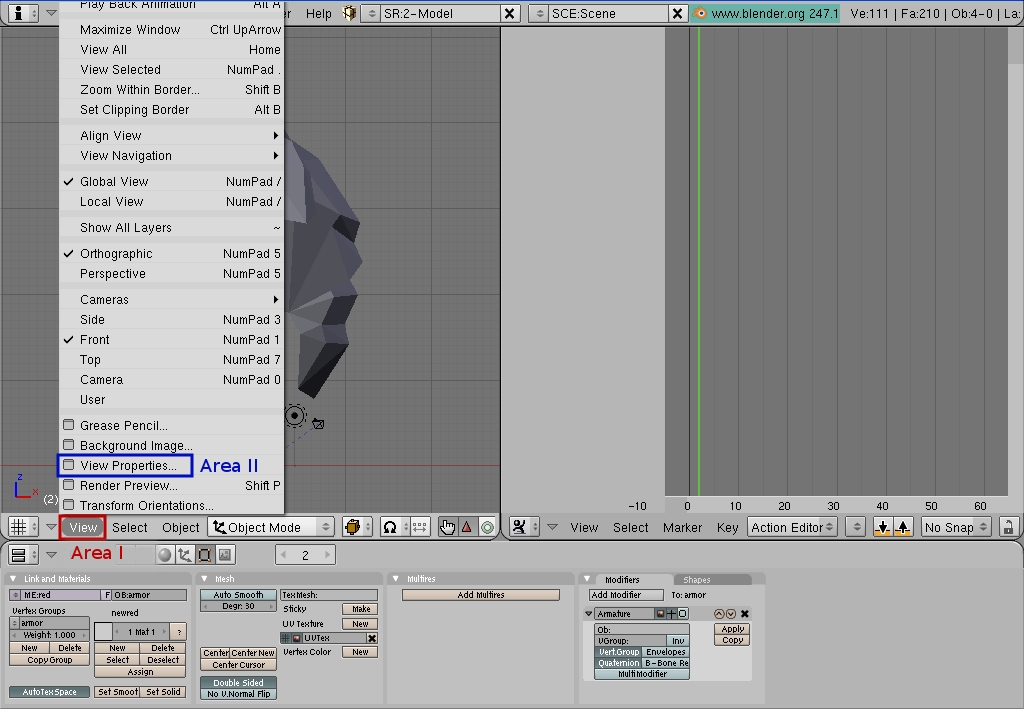
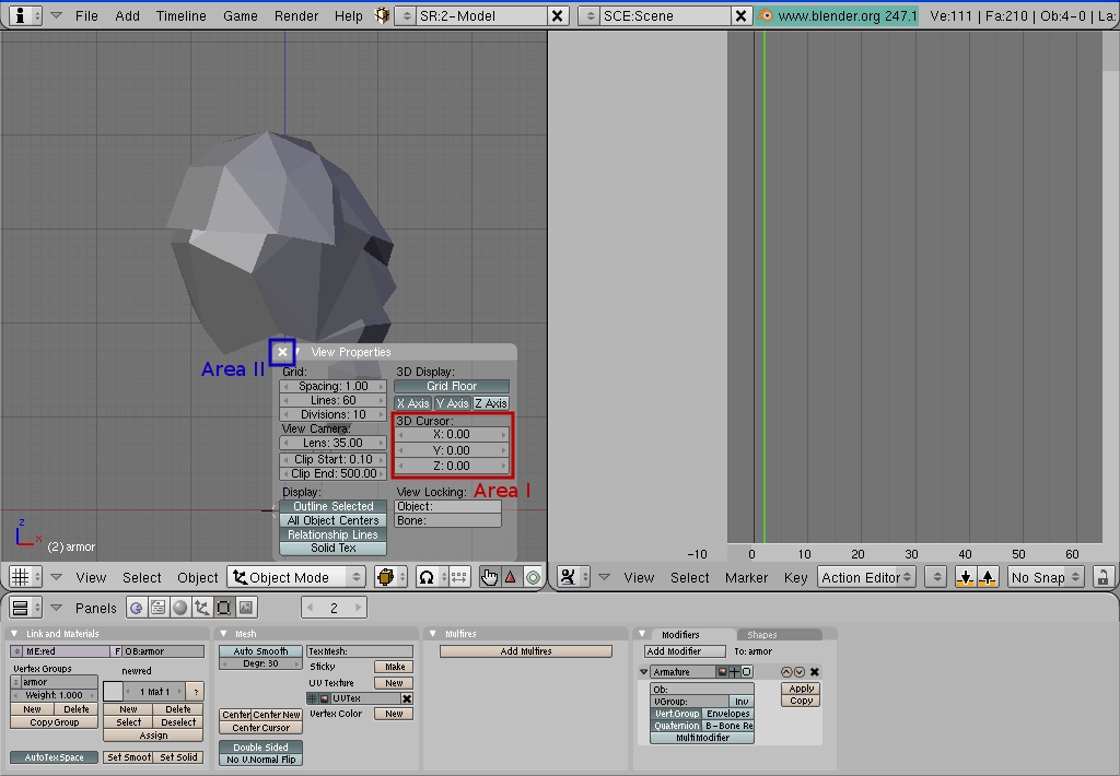
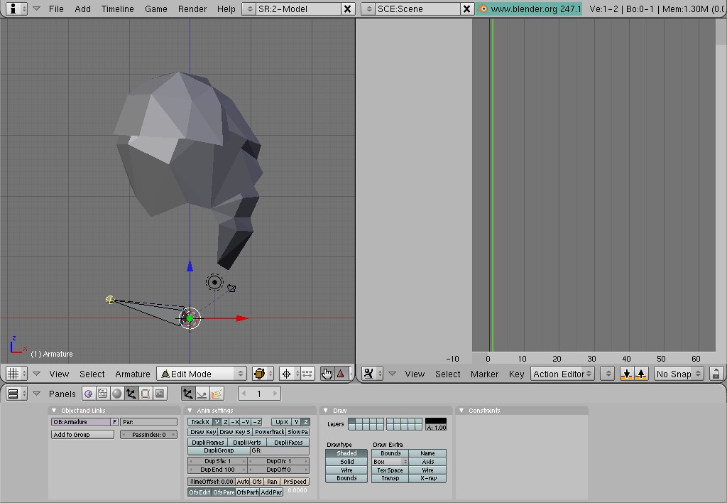
First of all let's check position of 3D Cursor. Any new object in a scene will be automatically placed (or "spawned" if you wish) where 3D Cursor is. In our case we need to place our first bone right at the beginning of coordinates. To make sure 3D Cursor is where it suppose to be left-click on "View" menu item (Pic. 16b, Area I), choose and left-click on "View Properties" (Pic. 16b, Area II). A new semi-transparent window will appear within 3D View. Now you can set 3D Cursor's coordinates. Let's check current coordinates of 3D Cursor (Pic. 16c, Area I). If X, Y and Z values are not equal 0 (zero), change it to 0 (zero) by clicking on the field with numbers and typing 0 (zero). If all three coordinates are set to 0 (zero) already, simply close the window (Pic. 16c, Area II). |
 |
 |
Pic. 16b |
Pic. 16c |
|
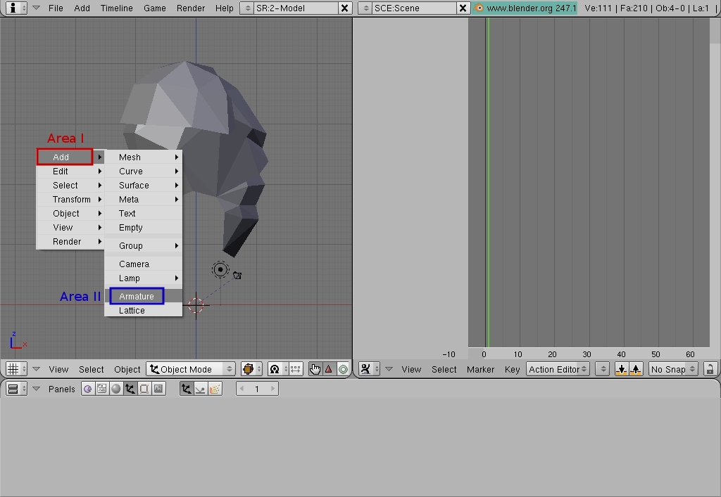
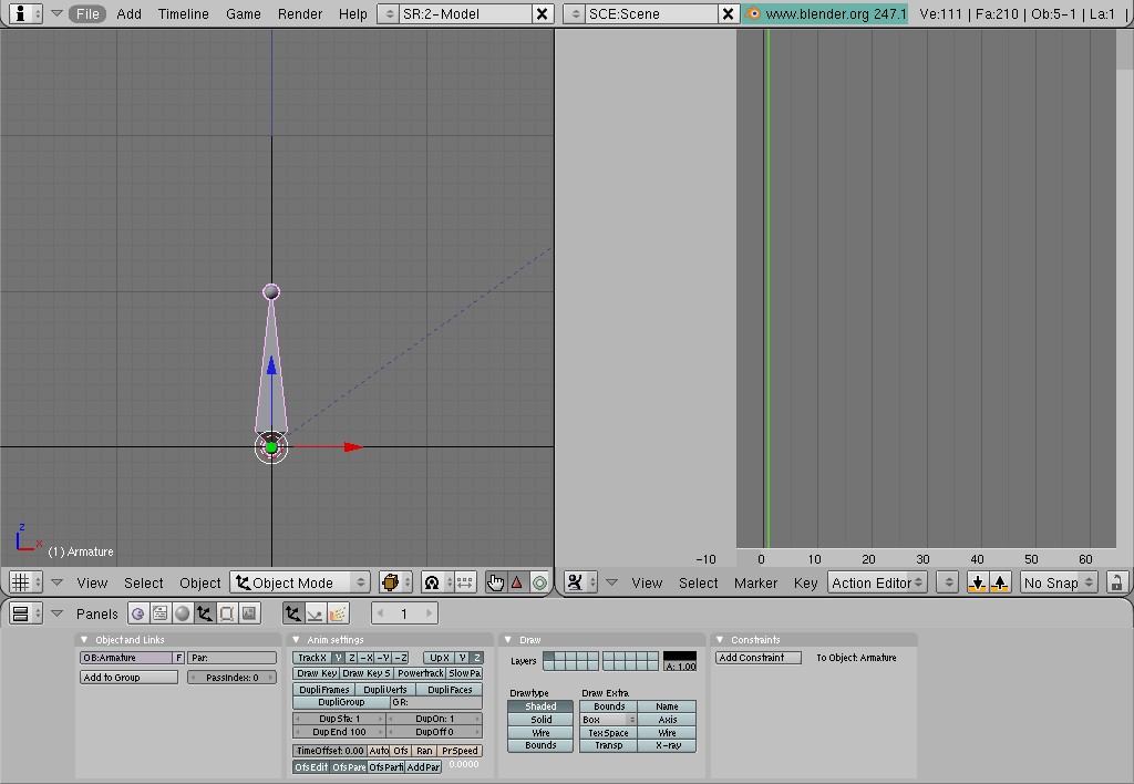
It's time to break add some bones :) Move mouse cursor into 3D View, press <Space bar>, choose "Add" menu item (Pic. 17, Area I), move mouse cursor to a newly appeared sub-menu, choose "Armature" (Pic. 17, Area II) and left-click on it. Armature (which is essentially a set of bones; right after being created, Armature contains only one bone) will be added to your scene at 3D Cursor. You probably will be unable to see it right away, because of the scale of your scene. We are going to fix that right now. Zoom in at 3D Cursor using mouse wheel for zoom and <Shift> + mouse wheel to pan the screen (press and hold mouse wheel while you holding <Shift>). Stop zooming one you have view as depicted on the Pic. 18. |
 |
 |
Pic. 17 |
Pic. 18 |
|
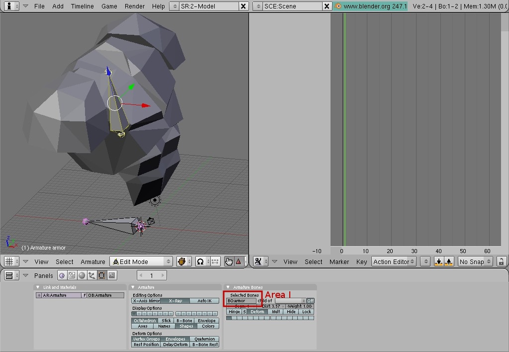
| Let's make that bone bigger. In order to do that you have to enter Edit Mode, where you will edit each bone that Armature is made of. Left-click on the Area I, Pic. 19, choose "Edit Mode" from the popped up menu and left-click on it. Now you are in the Edit Mode. Each bone is made out of body and two tips, one is at the narrow end of the bone's body (top tip currently) and another one is at the wide end of the bone (currently bottom tip). Right-click on the top tip of the bone (Area II, Pic. 19). It will become highlighted with yellow. Press <G>, then press <Z> and after that move mouse cursor up a bit to stretch the bone and left-click to finalize the operation (Pic. 20). |
 |
 |
Pic. 17 |
Pic. 18 |
|
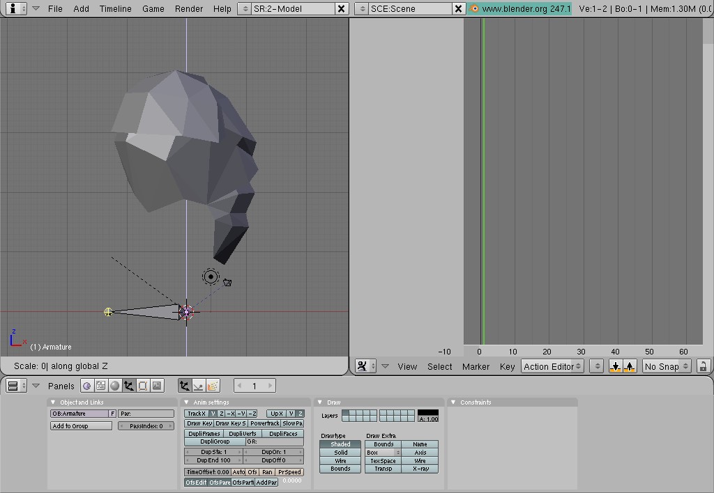
| This bone will be our root bone. Let's put it into horizontal position for easier visual identification. With the top tip still being selected press <G> and move it using mouse until it reaches position shown on the Pic. 21. To make the bone perfectly horizontal (it's not necessary, but it looks much nicer and cleaner that way) we are going to align selected tip of the bone with the tip that is at 3D Cursor's position. In order to do that we are going to move a pivot point or center of the selected tip into the position of 3D Cursor. Press <.> and you will see that top tip stayed selected (highlighted yellow), but the axis gizmo (center of the bone tip) moved into 3D Cursor's position (Pic. 22). Press <S> after that, then press <Z>, then press <0> (zero) and finally press <Enter> to finalize the operation (Pic. 23). Press <,> to return center of the tip where it belongs - to the middle of the selected bone tip. |
|
| While we were putting the bone into horizontal position, it rotated or rolled around it's axis of symmetry. In order to avoid any surprises further down the process, we need to clear that rotation and bring back roll angle to it's default value. With mouse cursor being within 3D View, press <A> to de-select everything and then press <A> again to select bone's body and both tips. Press <Ctrl> + <N> and left click on "Clear Roll (Z-axis Up)" (Pic. 24). |
 |
Pic. 24 |
|
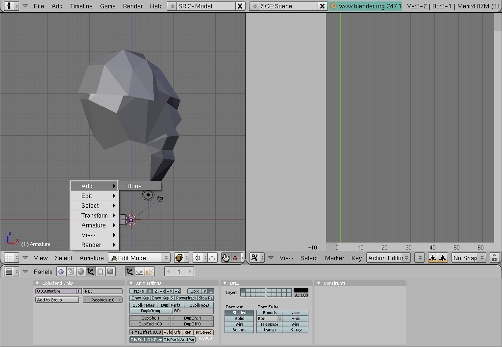
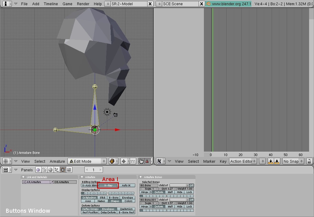
| Now we are going to create another bone that we will attach armor mesh to. Press <Space bar>, choose "Add" and then left-click on "Bone" (Pic. 25). You will get another bone added to your scene. As with the first bone, you are going to stretch it up a bit. Zoom in at 3D Cursor, right-click on the top tip of the bone to select it, press <G>, then <Z> and move mouse up until the bone with become a proper size (Pic. 27). Left-click to finalize the operation. Select both bones by pressing <A> twice (first time to de-select all and second time to select both). Bones should become highlighted with yellow (Pic. 29). By default you might have Buttons Window in the "Object Mode" (Pic. 27, Area I). If so, you need to switch Buttons Window into "Editing Mode". Press either <F9> with mouse cursor being within Buttons Window or press "Editing Mode" icon (Pic. 27, Area II). Locate button "X-Ray" in the Button Window and activate it by left-clicking on it (Pic. 29, Area I). |
|
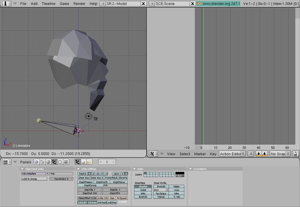
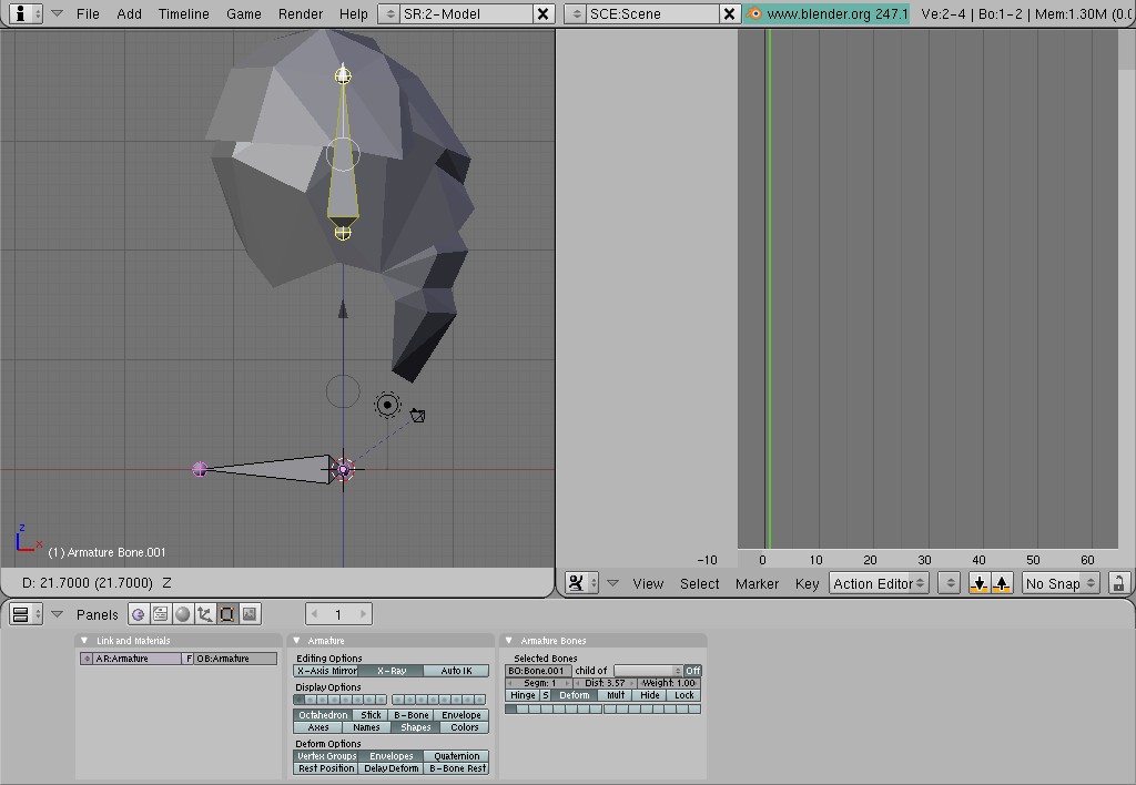
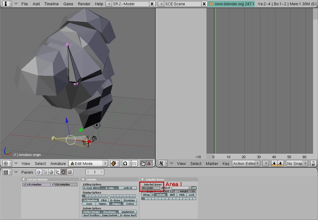
| Let's move our vertical bone up where we have our armor. Press <A> to de-select both bones, right-click on the body of the vertical bone (whole bone should become highlighted), press <G>, then <Z> and move mouse up until the bone reaches the position as on Pic. 30. Left-click to finalize the operation. Our next step will be rotating 3D View to see our armor in perspective. With mouse cursor being within 3D View, press and hold mouse wheel and move mouse around until you reach desired 3D View angle. Once you decided that it's good enough, release mouse wheel (Pic. 31). It's a good idea to name your bones. It's not very important when you have only two bones, but it's better for organization process and it will help you to develop a good habit of naming objects in your scenes. Press <A> and then right-click on our first bone (laying horizontally). Locate an input field for selected bones (Pic. 31, Area I), lift-click on it, erase the name you have there and type "origin". That is how we going to call first bone. The bone inside the armor is going to be called simply "armor". Press <A>, then right-click on the bone. Do the same sequence of actions that you have done for the "origin" bone, but instead of "origin" you need to type "armor" (Pic. 32, Area I). |
|
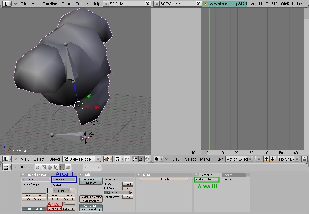
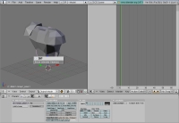
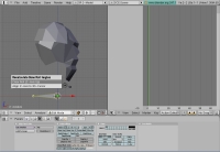
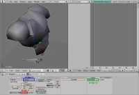
As you can see our armor is not "smoothed". It looks like it's made out of triangles and quads. We need for it to look continuously smooth. In order to do that we need to exit Edit Mode for our Armature. Left-click on the Area I, Pic. 19, choose "Object Mode" from the popped up menu and left-click on it. Now you are back to the Object Mode. Right-click on the armor mesh to select it (it will become highlighted with pink), locate "Set Smooth" button in the Buttons Window (Pic. 34, Area I) and left-click on it. Now our armor has continuous smooth surface (Pic. 34). Also don't forget to check the name of the mesh (Pic. 34, Area II). If it's not "armor", left-click in the field and rename it.
It's time to attach armor mesh to the Armature. First of all we are going to add Modifier called "Armature". Locate a button called "Add modifier" on the panel called "Modifiers" in the Buttons Window (Pic. 34, Area III). |
 |
Pic. 34 |
|
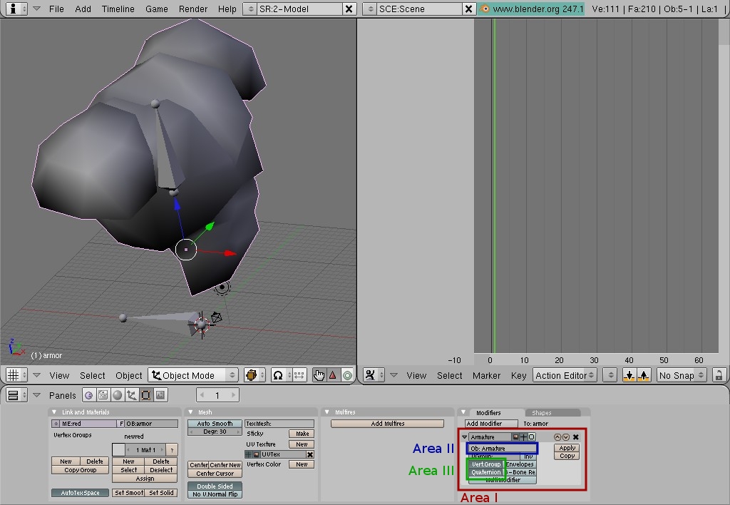
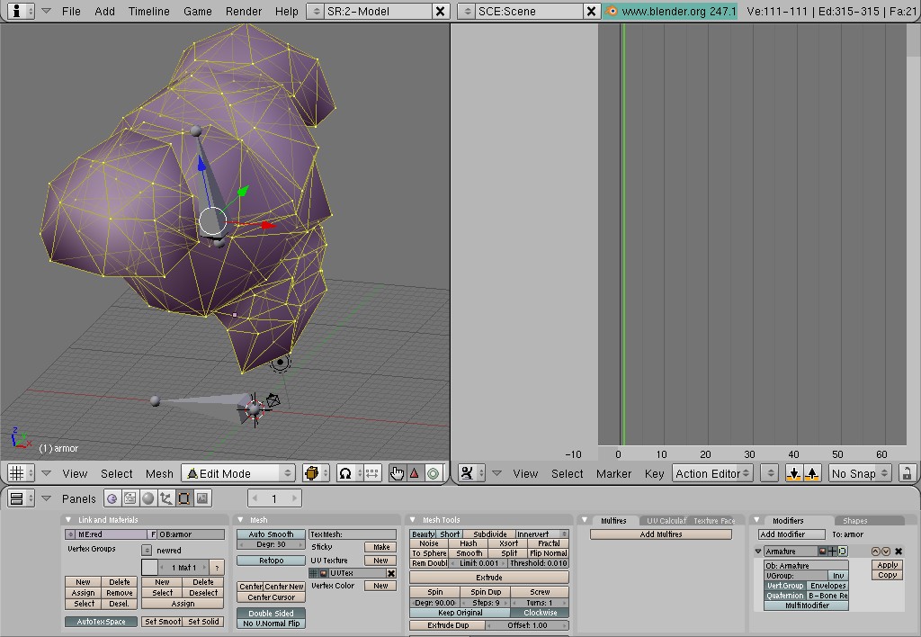
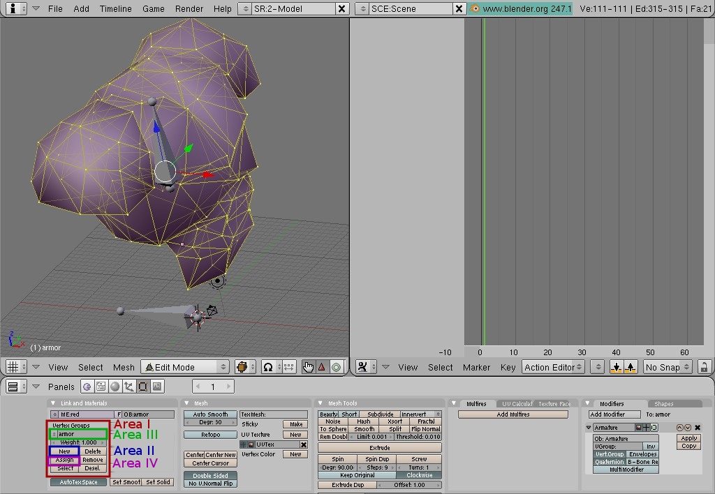
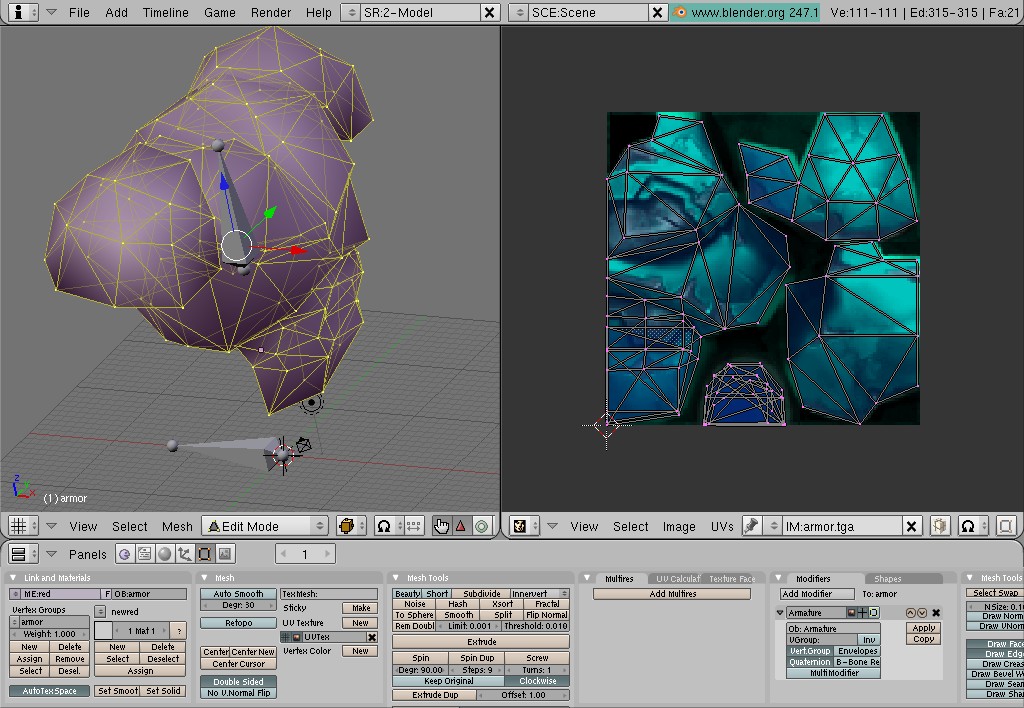
| Press "Add modifiers" button, choose and left-click on "Armature" from popped up menu. Modifier will be added to our armor mesh (Pic. 35, Area I). Locate field "Ob: " among modifier's parameters (Pic. 35, Area II), type "Armature" in the field and press <Enter> to finalize the operation (it's important to type the name "Armature" with capital "A"; you can use <Tab> to auto complete text input fields in Blender). Activate buttons "Vert. Group" and "Quaternion" as shown on the Pic. 35, Area III. Blender needs to know which vertices of armor mesh are going to be influenced by the "Armor" bone. We have to create a vertex group what will include all vertices that belong to the armor mesh. First of all we have to enter "Edit Mode" in 3D View to be able to select vertices. We are going to do that just like we did it with Armature earlier. Make sure that armor mesh is selected and if so, choose "Edit Mode" from the pop-up menu in the header of the 3D View (Pic. 17, Area I). The mesh should change it's color from gray to pink with edges and vertices highlighted with yellow (Pic. 36) If you are in the "Edit Mode" and your mesh is not pink and the edges and vertices are not yellow, you need to press <A> to select it all. Time to create a vertex group, call it "armor" (name has to be the same as name of a bone you are attaching mesh to) and assign selected vertices to that vertex group. Locate Vertex Group area in the "Links and Materials" panel in the Buttons Window (Pic. 37, Area I). Left-click on the button called "New" (Pic. 37, Area II) to create a default vertex group. Left-click in the field with name "Group", erase it and type "armor" (Pic. 37, Area III). Make sure all of the vertices are selected in 3D View and left-click button "Assign" (Pic. 37, Area IV). |
|
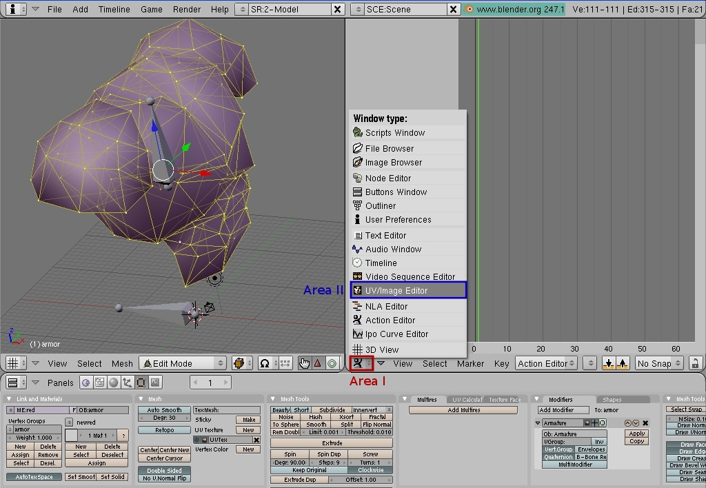
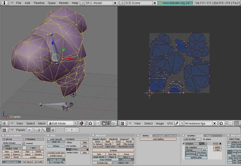
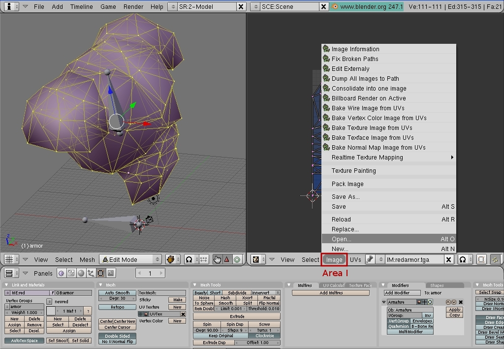
| We are half way through :D Let's apply texture to our armor. I have to note here that a texture we are going to apply to our mesh is going to show up in 3D View only and not in the Render Window in case you decide to render the scene. It needs to be done this way in order for the exporter to write proper shader name into .md5mesh file. To switch from Action Editor to UV/Image Editor, left-click on the icon at the bottom-left corner of the Action Editor view (Pic. 38, Area I). Choose "UV/Image Editor" from the pop-up menu (Pic. 38, Area II) and left-click on it. Now we have UV/Image Editor open (Pic. 39). To load a texture, left-click on the "Image" menu item (Pic. 40, Area I), choose "Open" and locate "armor.tga" file (it suppose to be at your QUAKE\armor\progs\ folder). |
|
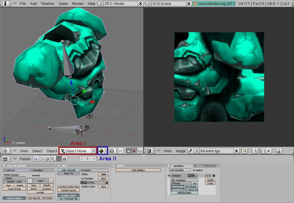
| Double left-click on it to load it up and it will appear in UV/Image Editor (Pic. 41). Still can't see it in 3D View? No problem. Switch from "Edit Mode" to "Object Mode" in 3D View (Pic. 42, Area I) and change view draw type to "Textured" (potato mode) by left-clicking on Area II (Pic. 42), choosing "Textured" and left-clicking on it. |
 |
 |
Pic. 41 |
Pic. 42 |
|
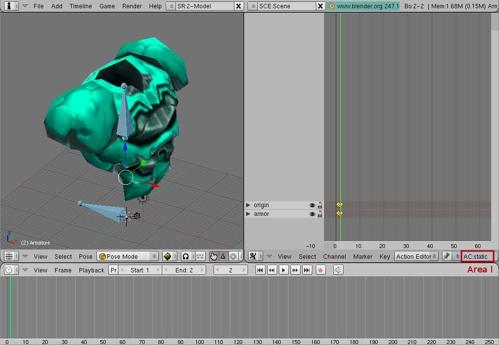
| In order to properly export mesh with bones from Blender into Doom 3 format, we have to have short animation done in our scene. How short? I would say 1 frame would be sufficient for a static object. We don't need to animate anything. We just have to add animation keys for our bones at the first frame of animation and at the last one. Switch back from UV/Image Editor to Action Editor (Pic. 43, Area I), switch from Button Window to Timeline Window by left-clicking on Area II (Pic. 43) and choosing "Timeline" from the pop-up menu. You need to set duration of animation and current animation frame. It's done by setting appropriate values in the Area III and Area IV respectively (Pic. 43). The first frame is frame 1, the last frame is frame 2 (duration is 1 frame) and the current frame is frame 1. In order for us to set keys for the bones we need to be in Pose Mode. Right-click on the bottom (root) bone to select the Armature (it will become highlighted with pink). Switch from "Object Mode" by left-clicking on the Area V (Pic. 43) and choose "Pose Mode". If any off the bones is selected (highlighted with blue), de-select it by pressing <A> and then select both bones by pressing <A> again (both bones should become highlighted with blue) (Pic. 43). |
 |
Pic. 43 |
|
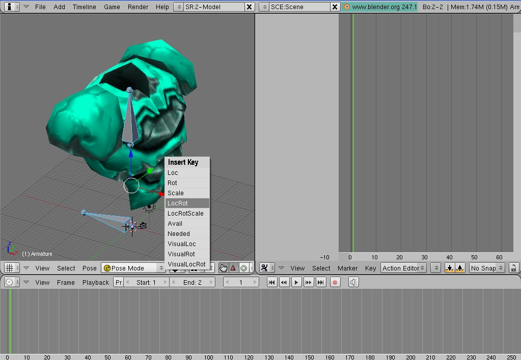
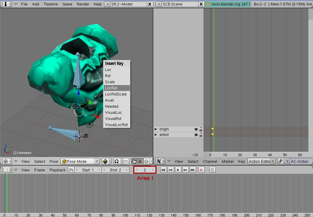
| Make sure that the current frame is frame 1. With mouse cursor being within 3D View, press <I> to insert animation keys, choose and left-click on LocRot in the pop-up menu (Pic. 44). Two little yellow bullets will appear in Action Editor. Make frame 2 current but left-clicking and typing "2" in the Area I (Pic. 45); press <Enter> to finalize the operation. Move mouse cursor into 3D View and insert animation keys one more time (Pic. 45). Another set of two bullets will appear in Action Editor (Pic. 46). Left-click on the Area I (Pic. 46), erase "Action" and type "static"; press <Enter> to finalize. |
|
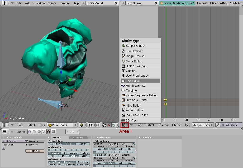
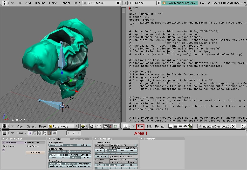
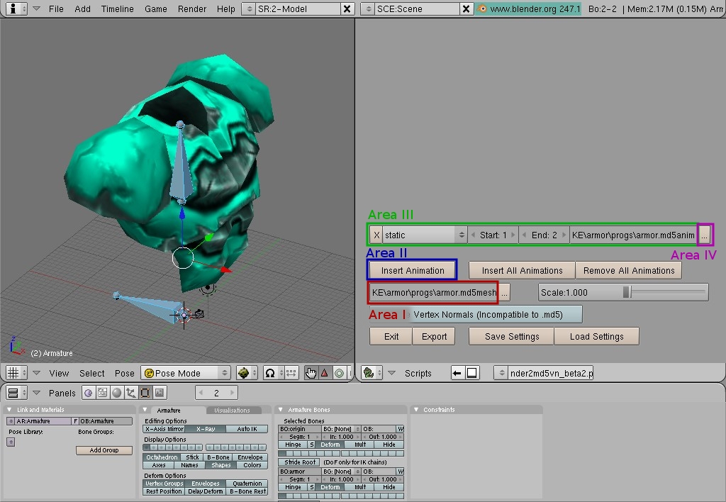
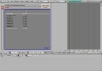
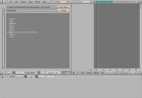
| We are almost done. Now we are going to export our armor into Doom 3 .md5 format. Switch from Action Editor to Text Editor (left-click on Area I, Pic. 47, choose "Text Editor" and left-click on it). Left-click on the "File" menu item (Area I, Pic. 48) and then on "Open". Locate exporter with filename "blender2md5vn_beta2.py" (if you downloaded Blender's build from my web site, it would be located in your Blender install folder in .blender\scripts\; otherwise get it here and save it in .blender\scripts) and double-click on it to load it. With mouse cursor within Text Editor window press <Alt> + <P> to execute the script. once executed successfully, it will look like on the Pic. 49. Left-click on Area I (Pic. 49) to set output folder and a file name for Doom 3 .md5mesh file. |
|
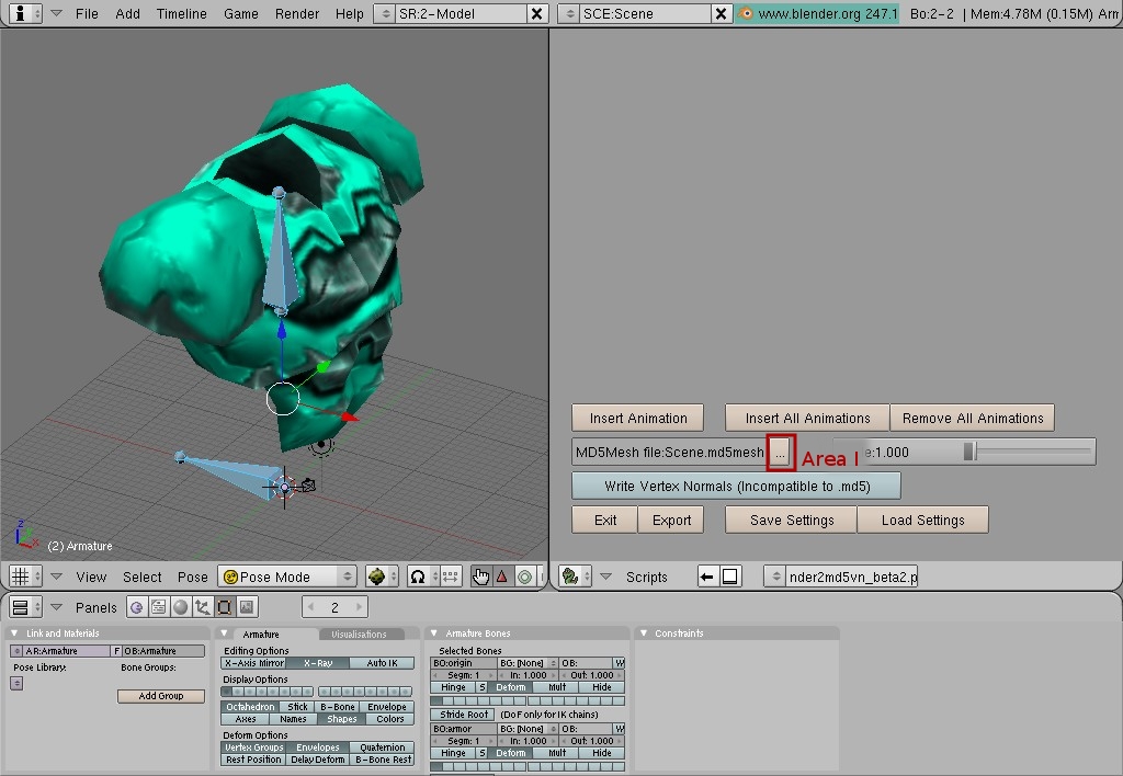
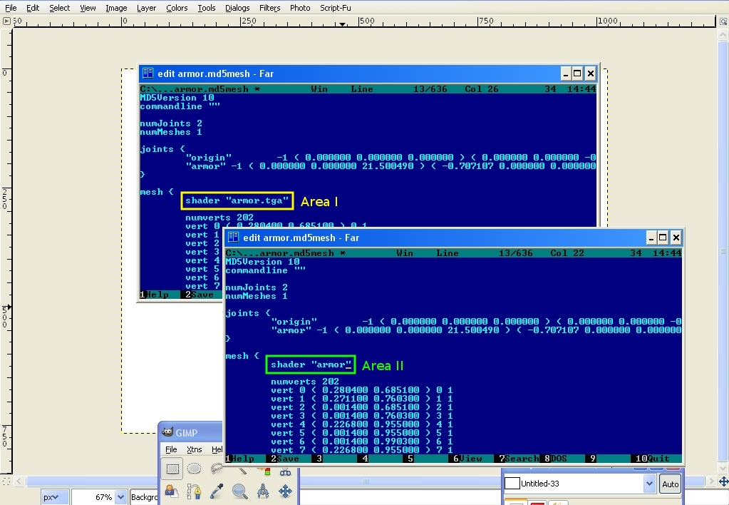
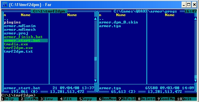
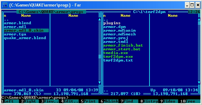
| Set it to "c:\tmrf2dpm\" and set file name to "armor.md5mesh" (Pic. 50, Area I). Left-click on "Insert Animation" button (Pic. 50, Area II). A new line will appear above that button with animation setting (Pic. 50, Area III). Make sure that the Start frame is 1 and the End frame is 2. Set output folder and a file name to "c:\tmrf2dpm\" and "armor.md5anim" respectively, by left-clicking on the Area IV (Pic. 50). Once it's all done and looks exactly like on the Pic. 50, press "Export" button and we are done with Blender. Before we will convert Doom 3 .md5 file to Dark Places .dpm format, we need to edit armor.md5mesh file and correct shader name. I use Far Manager to edit my text files (you can use anything you feel comfortable using). Open up armor.md5mesh that should be located in c:\tmrf2dpm\ and find a line that says: shader "armor.tga" (Pic. 51, Area I). Change it to: shader "armor" (Pic. 51, Area II). Save the file. There are two step in conversion process. First is when tmedia.exe reads .proj file and convert Doom3 files into single .tmdl file. Second step is when tmrf2dpm.exe takes .tmdl file and converts it to .dpm file. I included a file "armor.proj" with tmrf2dpm util which describes what does the util has to do with Doom 3 .md5 file. It's pretty much self-explanatory and you can use it as an example for other project. If you named your file correctly (you have to have armor.md5mesh, armor.md5anim, armor.proj), everything should go smoothly. Execute "armor_start.bat" and "armor_finish.bat" consequently (Pic. 52). |
|
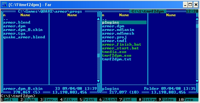
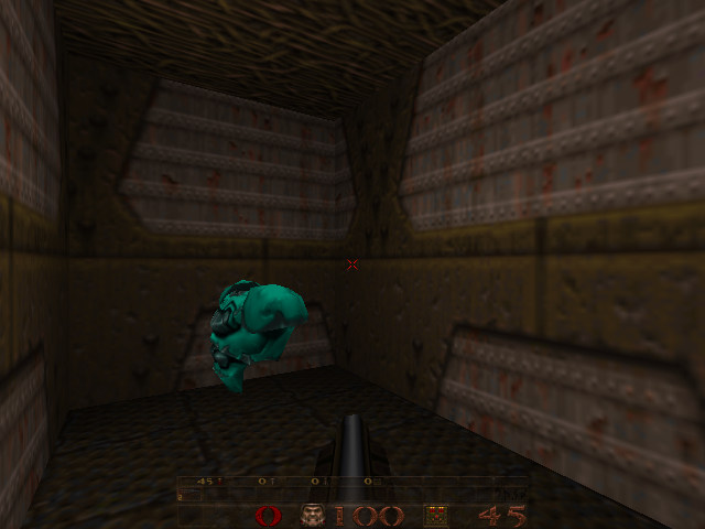
| After the util is done working you should have armor.tmdl and armor.dpm in your c:\tmrf2dpm\ folder. Copy "armor.dpm" file into QUAKE\armor\progs\ folder. Now besides .blend files in your QUAKE\armor\progs\ folder you suppose to have "armor.dpm", "armor.dpm_0.skin" and "armor.tga" files (Pic. 53). Rename "armor.dpm" into "armor.mdl" and "armor.dpm_0.skin" into "armor.mdl_0.skin" (Pic. 54). Execute darplaces.exe (or darkplaces_sdl.exe) with following command line parameters: "darkplaces.exe -game armor +map e1m1". Go to the place where green armor suppose to be and you will see you brand new Quake 3 armor hanging in there (Pic. 55). I must note that it's not going to be spinning as original one due to inability to set proper bit flags inside of .dpm models. However you can make it bob and rotate with only one line of QuakeC code: "self.modelflags = MF_ROTATE", but let's leave it for another tutorial :) |
|
| |
All rights reserved. (C) Alexander V. Zubov, 2004-2008 |